Raspberry Pi OS
Raspberry Pi OS User Manual
This manual provides users with a quick start guide of Chipsee Raspberry Pi Computer (Abbreviated as RPC) running a Raspberry Pi OS (raspios-debian-buster, raspios-debian-bullseye). Through this manual, users can quickly understand the hardware resources; users can debug Raspberry Pi OS via serial, SSH, and VNC.
Revision |
Date |
Author |
Description |
|---|---|---|---|
V2.1 |
2021-04-28 |
Chipsee |
Revision |
V2.2 |
2023-11-09 |
Chipsee |
Update Supported Boards |
SUPPORTED BOARDS:
CS10600RA070
CS12800RA101
CS12720RA4050
CS10600RA4070
CS10600RA4070P-D
CS12800RA4101A
CS12800RA4101P
CS10768RA4121
CS19108RA4133
CS10768RA4150
CS19108RA4156
CS12102RA4170
CS12102RA4190
CS19108RA4215
CS19108RA4236
CSRA4BOX
PREBUILT IMAGES PACKAGE:
Below are the links to the prebuilt images for the Raspbian operating system on the various industrial Pi PC’s.
System Features
Note
Preparation
You will need to prepare the following items before you can start using the Prebuilt Images Package to re-flash the system.
Power Supply Unit (PSU) with the appropriate voltages, as follows:
These products: CS12720RA4050, CS10600RA070, CS10600RA4070, CS10600RA4070P-D, CSRA4BOX and CS12800RA101 requires a 6V to 36V power adapter. You must provide the power adapter since Chipsee does not ship these products with a power adapter.
The CS12800RA4101A RPC needs a 12V power adapter. Chipsee provides the power adapter.
The CS12800RA4101P, CS10768RA4121, CS19108RA4133, CS10768RA4150, CS19108RA4156, CS19108RA4215, CS19108RA4236 RPC need 12V to 36V power adapter.
Hardware Requirements
Chipsee Raspberry Pi®
PSU according to the instructions above
Mini-B USB OTG and MicroB USB Cable to download system images to CM3/CM3+/CM4 based IPC’s.
USB to RS232 serial cable for serial debugging the Chipsee Raspberry Pi® product.
TF Card (SD Card) to create a bootable storage for re-flashing the system. Use the prebuilt files link above to re-flash the system.
If you use CM3 Lite/CM3 Lite+/CM4 Lite, you also need one SD card, 16GB at least.
Software Requirements
Raspberry Pi OS Prebuilt Images Package (from the link above)
XShell or other terminal emulation software
Note
If you want to change the system, you need 7zip, a Prebuilt image, balenaEtcher, and rpiboot.
You can use Xshell or other terminal emulation software to debug Chipsee Raspberry Pi products in Windows.
You can use VNC-Viewer to control Chipsee Raspberry Pi products over Ethernet.
Note
In this documentation, all the commands are executed with root user privileges.
Debug
In this document, we use Xshell to debug the Chipsee Raspberry Pi products. You can also use other tools such as Putty or another terminal emulation software.
Serial Debug
The RS232_0 is configured as debug console by default on all Chipsee Raspberry Pi products. You can use it to debug directly, and the default user and password is [ pi / raspberry ]. Use the session properties as shown on the figure below.

Figure 1038: Session Properties
If you need to change the debug serial to normal serial, follow these steps:
Open and edit /boot/cmdline.txt file.
In the file, remove the line console=ttyAMA0, 115200. Save and close file.
Reboot the RPC.
SSH Debug
To perform SSH debugging on the Chipsee Raspberry Pi® product, you must first connect the product to the Internet.
Continue the debugging by follow these steps:
Get the IP address of the Chipsee Raspberry Pi® product.
- Enable the SSH feature in the Chipsee Raspberry Pi® product by running the following command in debug console:
$ sudo raspi-config

Interfacing Options -> SSH -> Yes
- If you don’t have a debug console, you can also use the GUI feature to enable SSH.


Figure 1039: Enabling SSH (GUI)
Open and configure XShell or use ssh tool in the PC directly
- In XShell, add a new session and set it as shown on the figure below.

Figure 1040: SSH Setting on Xshell
- Now we can perform SSH debugging using XShell

Figure 1041: SSH Debug
VNC Debug
You can use VNC-Viewer in Windows to control Chipsee Raspberry Pi product over Ethernet.
Continue the debugging by follow these steps:
- Enable the VNC feature in the Chipsee Raspberry Pi® product by running the following command in debug console:
$ sudo raspi-config

Interfacing Options -> VNC -> Yes
- If you don’t have a debug console, you can also use the GUI feature to enable VNC.


Figure 1042: Enabling VNC (GUI)


Downloading images
Boot Switch Configuration
Chipsee RPC supports booting from an integrated eMMC or an external TF Card (also known as the micro SD card).
Note
CS12800RA4101A and CS12800RA4101P only supports eMMC boot
The Compute Module (CM) version will determine the boot modes your product supports.
If you use CM with eMMC, you can only use eMMC boot. If you use CM Lite which has no eMMC, you can only use SD boot.
To boot from the SD Card, you must place the SD Card in SD0 slot. You can use the SD1 slot as external storage.
For CS10600RA070, CS12800RA101, and CS10600RA4070 products, you can download a new system to eMMC by: configuring the boot switch to USB position, inserting Mini-B USB cable, and then power the board. This will enable eMMC to work as a USB storage.
After the eMMC flash, you need to configure the boot switch to the eMMC position again.
If you need to use SD boot, you should configure the boot switch to the eMMC position.
For the CS12800RA4101A product, you can download a new system to eMMC by: inserting a Micro-B USB cable, pressing the VOL+ button, and then power the board to enable eMMC to work as a USB storage. If you use C111 Version, you should press Boot Mode button.
For the CS12800RA4101P product, you can download a new system to eMMC by: inserting a Micro-B USB cable, pressing the Boot DIP button, and then power the board to enable eMMC to work as a USB storage.
The next sections explain in detail the steps in downloading a new system to eMMC.
Prebuilt image
Chipsee Raspberry Pi products use the Raspberry Pi official system as a base and add some modules and drivers. You can get the driver and latest image by referring to https://github.com/Chipsee/industrial-pi#latest-system-images.
If you’re not using balenaEtcher, you’ll need to unzip the .img.xz file and get the image file (.img) to write to your SD card.
Writing images to the SD Card
Before you start, don’t forget to check your SD card size (at least 16GB).
You will need to use an image writing tool to install the downloaded image on your SD card.
Using balenaEtcher Tool
balenaEtcher is a graphical SD card writing tool that works on Mac OS, Linux and Windows, and is the easiest option for most users.
balenaEtcher also supports writing images directly from the .img.xz file, without any unzipping required.
To write your image with balenaEtcher, follow these steps:
Download and install the latest version of balenaEtcher.
Connect an SD card reader with the SD card inside.
Open balenaEtcher and select from your hard drive the Raspberry Pi® .img.xz file you want to write to the SD card.
Select the SD card you want to write your image to.
Review your selections and click ‘Flash!’ to begin writing data to the SD card.
Note
For Linux users, zenity might need to be installed on your machine for balenaEtcher to be able to write the image on your SD card.
Note
The image supports Chipsee all Industrial-Pi products but AIO-CM4-156, you should refer to the guide for your product. You should wait 2 ~ 5 minutes after flashed system as it needs time to detect the product to complete initial work. If a sound is heard, don’t worry, just wait it to boot.
Writing images to the eMMC
Before you start, don’t forget to check your eMMC size, and select one image. You also need to install rpiboot to enable eMMC to work as one USB storage in your PC.
Under Windows, an installer is available to install the required drivers and boot tool automatically.|br|
For those who just want to enable the Compute Module eMMC as a mass storage device under Windows, the stand-alone installer is the recommended option.
The write images to the eMMC, follow these steps:
Download and run the Windows installer rpitools to install the drivers and boot tool.
For CS10600RA070, CS12800RA101, and CS10600RA4070 products, plug your host PC Mini-B USB into the USB Downloader port, making sure the boot switch is set to the USB position.
For CS12800RA4101A product, plug your host PC Micro-B USB into the USB Slave port (can be also called USB Download Port), press and hold the VOL+ button, if you use C111 Version, press Boot Mode button.
For CS12800RA4101P product, plug your host PC Micro-B USB into the USB Slave port (can be also called USB Download Port), press and hold the Boot DIP button.
Power ON the board. Windows should now find the hardware and install the driver. For CS12800RA4101A and CS12800RA4101P, you can release the button now.
- Once the driver installation is complete, run the RPiBoot.exe tool that was previously installed. You can run RPiBoot.exe in Windows PowerShell, as shown on the figure below.

Figure 1046: RPIboot tool
After a few seconds, the Compute Module eMMC will pop up under Windows as a disk (USB mass storage device).
Refer to Writing images to the SD Card to flash system to eMMC (like the SD card in Windows).
If process completes, power OFF the board and ensure the boot switch is set to eMMC position. Power ON to use the new system.
For CS12800RA4101A, ignore repositioning the boot switch, a reboot will be ok.
To learn more, visit the following link: https://www.raspberrypi.org/documentation/hardware/computemodule/cm-emmc-flashing.md
Note
The image supports Chipsee all Industrial-Pi products but AIO-CM4-156, you should refer to the guide for your product. You should wait 2 ~ 5 minutes after flashed system as it needs time to detect the product to complete initial work. If a sound is heard, don’t worry, just wait it to boot.
System Resource
SD Card/USB
SD Card is for external storage and needs to be placed in the SD1 port. The SD0 port is used by boot.|br| SD Card and USB Storage support hot plug. They will be automatically mounted on /media/pi/. For CS12800RA4101A and CS12800RA4101P, there is only one SD slot.
Serial Port
Chipsee Raspberry Pi® boards support RS232 and RS485. Check the table below to know more about the serial port on different boards.
Ports |
Name |
Node |
Protocol |
|---|---|---|---|
1 |
RS232_0 |
/dev/ttyAMA0 |
RS232 |
2 |
RS232_1/RS485_1 |
/dev/S0 |
RS232/RS485 |
Note
RS232_1/RS485_1 uses the same UART pins from the CPU, so they use the same device node. You can only use one at a time. RS485 signal has been mounted on the 120Ω Matched Resistor.
There is one GPIO that is used by RS485. You can control it to enable and disable RS485 to send and receive. Check the tables below.
GPIO |
Initial |
Control |
Function |
|---|---|---|---|
GPIO34 |
$ echo 34 > /sys/class/gpio/export $ echo out > /sys/class/gpio/gpio34/direction |
$ echo 1 > /dev/rs485con |
Enable send |
Disable receive |
|||
$ ln -s /sys/class/gpio/gpio34/value /dev/rs485con |
$ echo 0 > /dev/rs485con |
Enable receive |
|
Disable send |
Ports |
Name |
Node |
Protocol |
|---|---|---|---|
1 |
CPU_RS232_0 |
/dev/ttyAMA0 |
RS232 |
2 |
CPU_RS232_1 |
/dev/ttyS0 |
RS232 |
3 |
RS232_1 |
/dev/ttyUSB0 |
RS232 |
4 |
RS232_2 |
/dev/ttyUSB1 |
RS232 |
5 |
RS485_3 |
/dev/ttyUSB2 |
RS485 |
6 |
RS485_4 |
/dev/ttyUSB3 |
RS485 |
Ports |
Name |
Node |
Protocol |
|---|---|---|---|
1 |
RS232_0 |
/dev/ttyAMA0 |
RS232 |
2 |
RS232_2 |
/dev/ttyAMA1 |
RS232 |
3 |
RS232_3 |
/dev/ttyAMA2 |
|
4 |
RS485_3 |
/dev/ttyAMA2 |
RS485 |
5 |
RS232_5 |
/dev/ttyAMA3 |
|
6 |
RS485_5 |
/dev/ttyAMA3 |
RS485 |
- 1(1,2)
This channel does not output data by default. You can customize the channel to RS232 with port 4 and port 6 disabled.
Ports |
Name |
Node |
Protocol |
|---|---|---|---|
1 |
RS232_0 |
/dev/ttyAMA0 |
RS232 |
2 |
RS232_1 |
/dev/ttyAMA1 |
RS232 |
3 |
RS485_2 |
/dev/ttyAMA2 |
RS485 |
Ports |
Name |
Node |
Protocol |
|---|---|---|---|
1 |
RS232_0 |
/dev/ttyAMA0 |
RS232 |
2 |
RS232_2 |
/dev/ttyAMA1 |
RS232 |
3 |
RS232_3 |
/dev/ttyAMA2 |
RS485 |
4 |
RS232_5 |
/dev/ttyAMA3 |
RS485 |
You can install cutecom to test the serial port:
$ sudo apt-get install cutecom
Only root user and use the serial port:
$ sudo cutecom
GPIO
There are 8 GPIOs, 4 Output, and 4 Input, they are all isolated. You can control the output or input pin voltage by feeding the VDD_ISO suite voltage. The pin voltage should be from 5V to 24V. Refer to the tables below for a detailed port definition:
Function |
Device Node |
GPIOD line |
|---|---|---|
IN4 |
/dev/chipsee-gpio8 |
3 |
IN3 |
/dev/chipsee-gpio7 |
2 |
IN2 |
/dev/chipsee-gpio6 |
1 |
IN1 |
/dev/chipsee-gpio5 |
0 |
OUT4 |
/dev/chipsee-gpio4 |
4 |
OUT3 |
/dev/chipsee-gpio3 |
5 |
OUT2 |
/dev/chipsee-gpio2 |
6 |
OUT1 |
/dev/chipsee-gpio1 |
7 |
Isolated GND |
NC |
NC |
Isolated VDD(5V-24V) |
NC |
NC |
- Control OUT1 by setting it high or low
$ echo 1 > /dev/chipsee-gpio1    // set OUT1 high

$ echo 0 > /dev/chipsee-gpio1    // set OUT1 low
- Get IN1 value
$ cat /dev/chipsee-gpio5 // value 1 indicate high, value 0 indicate low
- Use libgpiod to control the GPIO
# uncomment the following lines in /opt/chipsee/chipsee-init.sh first
## GPIO
#num=1
#for i in $OUT; do
#[ ! -d /sys/class/gpio/gpio$i ] && echo $i > /sys/class/gpio/export
#echo out > /sys/class/gpio/gpio$i/direction
#chmod a+w /sys/class/gpio/gpio$i/value
#ln -sf /sys/class/gpio/gpio$i/value /dev/chipsee-gpio$num
#num=`expr $num + 1`
#done
#sleep 1
#for i in $IN; do
#[ ! -d /sys/class/gpio/gpio$i ] && echo $i > /sys/class/gpio/export
#echo in > /sys/class/gpio/gpio$i/direction
#chmod a+r /sys/class/gpio/gpio$i/value
#ln -sf /sys/class/gpio/gpio$i/value /dev/chipsee-gpio$num
#num=`expr $num + 1`
#done

# reboot to use libgpiod
$ sudo reboot

# install gpiod
$ sudo apt-get install libgpiod-dev gpiod

# compile test file
$ wget -c https://chipsee-tmp.s3.amazonaws.com/SourcesArchives/HARDWARETEST/gpiotest.c
$ gcc gpiotest.c -o gpiotest -lgpiod
$ ./gpiotest
Relay
There is one Relay on CS12800RA4101A. For a detailed port definition, please refer to the table below.
Ports |
Name |
Node |
Protocol |
|---|---|---|---|
8 |
Relay_NO |
GPIO17 |
Normal Open |
9 |
Relay_COM |
GPIO17 |
GND |
10 |
Relay_NC |
GPIO17 |
Normal Close |
- Initialize GPIO17 to output
$ echo 17 > /sys/class/gpio/export

$ echo out > /sys/class/gpio/gpio17/direction
- Enable Relay NO short-circuit Relay COM
$ echo 1 > /sys/class/gpio/gpio17/value
- Enable Relay NC short-circuit Relay COM
$ echo 0 > /sys/class/gpio/gpio17/value
BUZZER
The Chipsee Raspberry Pi boards have one buzzer. We have created one symbol link to /dev/buzzer. You can control it as follows:
$ echo 1 > /dev/buzzer    //enable buzzer

$ echo 0 > /dev/buzzer    // disable buzzer
Backlight
We use one PWM to control the backlight for Chipsee Raspberry Pi boards, You can use follow commands to control the backlight.
- Get the supported max brightness:
$ cat /sys/class/backlight/pwm-backlight/max_brightness
- Set brightness:
$ echo 50 > /sys/class/backlight/pwm-backlight/brightness
4G
Note
SIM card does NOT support hot plug. Power off before inserting/removing SIM card.

SIM Card Direction (7 inch product)

SIM Card Direction (10 inch and above products)
- You can use 4G on Chipsee Raspberry Pi products. If the 4G module is Quectel EC20, you can use linux-ppp-scripts to connect to internet.
$ sudo apt update
$ sudo apt install ppp
$ sudo ifconfig wwan0 down
$ cd linux-ppp-scripts/
$ sudo ./quectel-pppd.sh <Serial Port> <APN> <username> <password>

For example,
$ sudo ./quectel-pppd.sh /dev/ttyUSB3 3gnet test test

or no username and password
$ sudo ./quectel-pppd.sh /dev/ttyUSB3 3gnet

disconnect 4g
$ cd linux-ppp-scripts/
$ ./quectel-ppp-kill
- If you use EC20 with GPS function, you can enable and get data in the following way.
Open one terminal to catch data: cat /dev/ttyUSB1
- If you use EC20 with GPS function, you can enable and get data in the following way.
- Open another terminal to config and enable:
$ microcom –s 9600 /dev/ttyUSB2
AT+QGPSCFG=”gpsnmeatype”,1
AT+QGPS=1 // enable GPS, wait some minutes, you can get date from fist terminal.
AT+QGPSEND // disable GPS
Don’t forget to use one GPS ANT.
CAN Bus
There is one channel CAN bus on CS12800RA101/CS10600RA4070/CS12800RA4101P. You can install can-utils and use them to test CAN. But you must add one 120Ω resistor between CAN_H and CAN_L on one of the two Boards, as shown on the figure below.
Note
The Chipsee IPC does not mount the 120Ω matched resistor on all CAN signals by default.
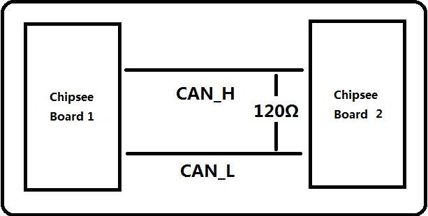
Figure 1047: Connecting CAN
Here are a few examples to test CAN by using CAN units
- Install can-utils
$ sudo apt install can-utils
- Set the bit-rate to 50Kbits/sec with triple sampling using the following command (use ROOT user):
$ sudo ip link set can0 type can bitrate 50000 triple-sampling on
- Bring up the device using the command:
$ sudo ip link set can0 up
- Transfer packets
Transmit 8 bytes with standard packet id number as 0x10
$ sudo cansend can0 -i 0x10 0x11 0x22 0x33 0x44 0x55 0x66 0x77 0x88
Transmit 8 bytes with extended packet id number as 0x800
$ sudo cansend can0 -i 0x800 0x11 0x22 0x33 0x44 0x55 0x66 0x77 0x88 - e
Transmit 20 8 bytes with extended packet id number as 0xFFFFF
$ sudo cansend can0 -i 0xFFFFF 0x11 0x22 0x33 0x44 0x55 0x66 0x77 0x88 -e --loop=20
For the latest system, we use the following commands
$ sudo cansend can0 5A1#11.2233.44556677.88
$ sudo cansend can0 1F334455#1122334455667788
- Receive data from CAN bus
$ sudo candump can0
- Bring down the device
$ sudo ip link set can0 down
Wi-Fi
The Chipsee Raspberry Pi boards support RTL8723BU/RTL8723DU chip Wi-Fi. The CS10600RA070/CS12800RA101 have an onboard RTL8723BU Wi-Fi chip. The CS10600RA4070/CS12800RA4101A/CS12800RA4101P have no onboard Wi-Fi by default so you can use the USB Wi-Fi dongle to enable the Wi-Fi.
Zigbee
The CS10600RA4070/CS12800RA4101A/CS12800RA4101P boards have an onboard ZigBee chip CC2531. Its device node in the system is /dev/ttyACM0. We use zigbee2mqtt project firmware by default. Check the following link to learn more about this project: Zigbee2mqtt
Note
The Zigbee module is not mounted by default.
Camera
The camera port CAM is compatible with Raspberry pi. Please refer to the following link to learn how to attach a camera: https://www.raspberrypi.org/documentation/hardware/computemodule/cmio-camera.md
Chipsee-init shell
We use one chipsee-init.sh as an initial shell which is placed in /opt/chipsee/chipsee-init.sh.
We initialize the GPIO/Buzzer and other configs in it. If you want to change it, please be careful.
Do a backup first before you modify anything. This script will generaged one log file which located on /var/log/chipsee-init.sh.log.
If your device has booting issues, you can send Chipsee® the file to help you find out what happened.
Disclaimer
This document is provided strictly for informational purposes. Its contents are subject to change without notice. Chipsee assumes no responsibility for any errors that may occur in this document. Furthermore, Chipsee reserves the right to alter the hardware, software, and/or specifications set forth herein at any time without prior notice and undertakes no obligation to update the information contained in this document.
While every effort has been made to ensure the accuracy of the information contained herein, this document is not guaranteed to be error-free. Further, it does not offer any warranties or conditions, whether expressed orally or implied in law, including implied warranties and conditions of merchantability or fitness for a particular purpose. We specifically disclaim any liability with respect to this document, and no contractual obligations are formed either directly or indirectly by this document.
Despite our best efforts to maintain the accuracy of the information in this document, we assume no responsibility for errors or omissions, nor for damages resulting from the use of the information herein. Please note that Chipsee products are not authorized for use as critical components in life support devices or systems.
Technical Support
If you encounter any difficulties or have questions related to this document, we encourage you to refer to our other documentation for potential solutions. If you cannot find the solution you’re looking for, feel free to contact us. Please email Chipsee Technical Support at support@chipsee.com, providing all relevant information. We value your queries and suggestions and are committed to providing you with the assistance you require.