Linux Qt 5.5 OS
Chipsee Linux Qt 5.5 OS User Manual
This manual provides users with a fast guide of Chipsee Industrial Computer (Abbreviate as IPC) about Linux Qt 5.5 OS development. Through this manual, users can quickly understand the hardware resources; users can build a complete compilation of Linux development environment; users can debug Linux Qt 5.5 OS via serial and Internet.
Revision |
Date |
Author |
Description |
|---|---|---|---|
V1.1 |
2021-12-30 |
Randy |
Revised |
V1.0 |
2018-05-14 |
Madi |
Initial Version |
SUPPORTED BOARDS:
CS10600U070
PREBUILT FILES PACKAGE:
Below is the link to the prebuilt images for the Linux Qt operating system on the various industrial PC.
prebuilt-cs10600u070v1-emmc-20210719.tar.gz
System Features
Feature |
Comment |
|---|---|
Kernel |
Kernel 3.14.52 |
Bootloader |
Uboot 2015.04 |
System |
Linux Qt 5.5 |
Python |
Python 2.7.9 |
Qt |
Qt 5.5.1 |
Desktop |
matchbox |
user/password |
[root/root] |
Preparation
You will need to prepare the following items before you can start using the Prebuilt Files Package to re-flash the system.
Power Supply Unit (PSU) with the appropriate voltages, as follows:
The CS10600U070 product needs a 6V to 36V power adapter.
You need to prepare the Power Adapter by yourself
Hardware Requirements
Chipsee Industrial PC
PSU according to the instructions above
USB-to-serial or other serial cable for debugging
USB A-A cable (used only if the hardware configured as OTG)
Windows 7 PC
Mini-B USB OTG Cable
TF Card (at least 4GB) and card reader
Software Requirements
Linux Qt 5.5 OS Prebuilt Files Package (from the link above)
Xshell or other terminal emulation software
Useful tools for Qt development
Note
If you want to re-flash the system, you need the Prebuilt image package.
You can use Xshell or other terminal emulation software to debug Chipsee Industrial PC products in Windows.
You can use VNC-Viewer to to remote control Chipsee Industrial PC over Ethernet.
The cross-toolchain can compile a program for Chipsee Industrial PC.
Note
In this documentation, all the commands are executed with root user privileges.
Debug
In this document, we use Xshell to debug the Chipsee Industrial Computer. You can also use other tools such as Putty, Minicom, SecureCRT or any terminal emulation software.
Serial Debug
You can refer to the RS232/RS485/CAN Connector section under the EPC/PPC-A7-070HB-C manual to understand the serial ports of the IPC.
The debug serial port of Chipsee Industrial Computer is the first RS232 port. You can use it to debug directly, and the default user and password is [root/root].
You can use RS232_1_TXD, RS232_1_RXD, GND.
Follow these steps to perform serial debugging:
Connect your Windows PC to the Chipsee IPC over a serial cable. Please reference the
How To Connect Board By Serialmanual to connect your PC and Chipsee Industrial Computer over a serial cable.


SSH Debug
To perform SSH debugging on the Chipsee IPC, you must first connect the product to the Internet.
Continue the debugging by follow these steps:
Get the IP address of the Chipsee IPC product.
You can configure XShell or you can directly use the SSH tool in Linux OS. In this tutorial, we will use the XShell tool to perform SSH debugging.
- Open XShell and add a new session and set it as shown on the figure below.

Figure 358: SSH Setting
- Now we can perform SSH debugging using XShell.

Figure 359: SSH Debug
VNC Debug
You can use the VNC-Viewer software in Windows to control Chipsee IPC over Ethernet.


Downloading images
Boot Switch Configuration
CS-IMX6 has a boot configuration select switch, as shown on the figure below. You can use the boot select switch to change between three modes, namely:
TF Card
eMMC Boot
Download

Figure 364: Boot Mode Setup
SW Mode |
1 |
2 |
3 |
4 |
|---|---|---|---|---|
TF Card |
1 |
0 |
0 |
0 |
eMMC |
1 |
1 |
0 |
1 |
Download |
0 |
1 |
1 |
0 |
Note
The user can use both the pre-built Linux Qt 5.5 image files and the MFGTools software to download new images to the system, boot system and perform necessary software and hardware test.
Prebuilt Files Package
You can get the Prebuilt Files Package for each model from links mentioned at the beginning of this documentation. You can also get the Prebuilt Files Package from the DVD in /Linux Qt 5.5/Prebuilds folder. However, it may be outdated so always compare the versions (the last number in the filename is the release date).
The prebuilt package has the following content:
Contents |
Comment |
|---|---|
boot/imx6q-eisd.dtb |
TF Card boot dtb file |
boot/u-boot-sd.imx |
TF Card boot bootloader |
boot/zImage |
TF Card boot kernel file |
boot/logo.bmp |
TF Card boot logo file |
filesystem/rootfs-emmc-flasher.tar.bz2 |
TF Card boot rootFS |
mksdcard.sh |
Shell tools to make bootable TF Card |
README |
Simple guidelines |
S1.jpg |
Boot Switch Config Figure |
emmc-flash/emmc/rootfs.tar.bz2 |
RootFS in target eMMC |
emmc-flash/emmc/u-boot-emmc.imx |
Bootloader in target eMMC |
emmc-flash/emmc/zImage |
Kernel file in target eMMC |
emmc-flash/emmc/zImage_framebuffer |
Kernel file with frame-buffer |
emmc-flash/emmc/imx6q-eisd.dtb |
Dtb file in target eMMC |
emmc-flash/emmc/imx6q-eisd.dtb_framebuffer |
Dtb file with frame-buffer |
emmc-flash/emmc/logo.bmp |
Logo file in eMMC |
emmc-flash/mkemmc.sh |
Shell tool to download images to eMMC |
Note
The default
zImageandimx6q-sabresd.dtbfiles support ‘keep the logo from uboot to kernel’ but don’t support framebuffer.We also provide
zImage_framebufferandimx6q-eisd.dtb_framebufferfile versions that support the framebuffer function but do not support the ‘keep the logo from uboot kernel’ feature. If you need the framebufer, just rename these two files tozImageandimx6q-eisd.dtb.
Downloading Images by using the TF card
Follow the steps below to download images onto the eMMC by using the TF Card:
Copy the Prebuilt Files Package to a Linux environment (such as Ubuntu 14.04).
Insert the SD card into your computer. If you are using virtual machines, please ensure the SD card is mounted to the Linux operating system.
- Confirm the SD card mount point,
/dev/sdX,(e.g.,/dev/sdcor/dev/sdb, be sure to use the right one). In a Linux system, you can use the command below to find out what X is. $ sudo fdisk –l
- Confirm the SD card mount point,
Copy the
prebuilt-imxv1-csXXXXXfXXXvX-android6-emmc-YYYYMMDD.tar.gzto somewhere(such as $HOME) on the Ubuntu PC.- Extract the
prebuilt-imxv1-csXXXXXfXXXvX-android6-emmc-YYYYMMDD.tar.gz $ tar -xzvf prebuilt-imxv1-csXXXXXfXXXvX-android6-emmc-YYYYMMDD.tar.gz
- Extract the
- Go to the folder
$ cd prebuilt-imxv1-csXXXXXfXXXvX-android6-emmc-YYYYMMDD
- Use the following command to flash the Linux Qt 5.5 OS to the SD card
$ sudo ./mksdcard.sh --device /dev/sd<?>
Note
sd<?> means the SD card mount point, (e.g.,
/dev/sdcor/dev/sdb) in Ubuntu system.The recommended SD card should be Sandisk Class4 level SD card or above.
The bootable SD Card is now ready. Power OFF the industrial PC and insert the SD Card.
Set the switch S1 to TF card boot mode. (refer to Boot Switch Configuration above)
Connect the industrial PC to PC via COM1. Power ON the IPC.
After 20 minutes, if the LED on industrial PC stays lit, flashing is completed. Using COM1, you can also find this message >>>>>>> eMMC Flashing Completed <<<<<<< which indicates that the system image was downloaded correctly to the eMMC.
Power OFF and set the switch S1 to eMMC boot mode. (refer to Boot Switch Configuration above)
System Resource
TF Card/USB Disk
The TF Card and USB Storage supports hot-plug. These devices will be automatically mounted on /run/media/mmcblk0P*, as shown in the figure.

Figure 365: TF Card
Note
The TF card and USB Storage do not support NTFS format. Please format it to FAT32 first before plugging into IPC.
Network
This system uses a networking service to control Ethernet and uses wpa_supplicant to control the WIFI network.
Wired Ethernet
You can get the IP address from the following application, as shown on the figure below.

Figure 366: Wired Connection

Figure 367: Ethernet Information
Wi-Fi
You can configure the Wi-Fi using these methods:
Config Wi-Fi by GUI
Config Wi-Fi by Command
Config Wi-Fi by GUI
Click the terminal on the desktop
Use the following command to generate network config information.
# wpa_passphrase "Chipsee" "1chipsee234567890"
Replace the information in /etc/wpa_supplicant.conf by setting the
ssid=Chipseeandpsk=1chipsee234567890, as shown on the figure below.

Figure 368: Wi-Fi Config File
Open the Wi-Fi icon on the desktop, then click the Enable button. Wait for some time to get the Wi-Fi working. The Wi-Fi is working when the network tab displays the WIFI Enabled! message, as shown on the figure below.

Figure 369: Wi-Fi Enable
Config Wi-Fi by Command
Use the command below to enable Wi-Fi.
# wifienable.sh
List available network and remove default if exist using these commands
# wpa_cli list_network
# wpa_cli remove_network
# wpa_cli scan
# wpa_cli scan_result // get latest scan results
# wpa_cli ap_scan 1
Add a new network and list added network using these commands
# wpa_cli add_network
# wpa_cli list_network
Set SSID, Password, and key management using these commands
# wpa_cli set_network 0 ssid "Chipsee"
# wpa_cli set_network 0 key_mgmt WPA-PSK
# wpa_cli set_network 0 psk "1chipsee234567890"
Enable the
network 0with this command
# wpa_cli select_network 0
Save config
# wpa_cli save_config
Re-enable Wi-Fi
# wifienable.sh
Sound Test
You can use the command below to record music. The -d parameter means interrupt after # seconds. In this example, -d is equal to 18 seconds.
$ sudo arecord -N -M -r 44100 -f S16_LE -c 2 -d 18 test.wav
You can use the command below to playback the recorded sound above.
$ sudo aplay -N -M test.wav
You can also use the QT Test Application to record and playback audio.
On the QT Test Application desktop, click on the HT button to perform a hardware test, as shown on the figure below.

Figure 370: Hardware Test
You can click the Audio button to playback audio. You can also click the Record button to record 18 seconds of audio then the application will playback the audio automatically.

Figure 371: Audio Test
Serial Port
There are five serial ports on the Chipsee IPC: 2 x RS232 and 3 x RS485 (can be customised). Refer to the table below for the available serial device nodes.
The default serial port configuration is 2 x RS232, 2 x RS485, 1 x RS485 which is shared with Bluetooth.
Contact us if you need help with changing the default serial port configuration
Ports |
Device Node |
|---|---|
COM1(RS232, Debug) |
/dev/ttymxc0 |
COM2(RS485) |
/dev/ttymxc1 |
COM3(RS232) |
/dev/ttymxc2 |
COM4(RS485) |
/dev/ttymxc3 |
COM5(RS485) |
/dev/ttymxc4 |
Note
If you use COM2(RS485), you can’t use Bluetooth because COM2(RS485) share pin with Bluetooth.
You can test the serial port by using the HT_Serial Application in the desktop, as shown on the figure below.

Figure 372: HT_Serial Test

Figure 373: HT_Serial Test
CAN Bus
Chipsee Industrial PC is equipped with two CAN busses (CAN1 and CAN2). Two devices can be interconnected. You can test the CAN buses by using the HT application but you must add one 120Ω resistor between CAN_H and CAN_L on one of the two Boards, as shown on the figure below.
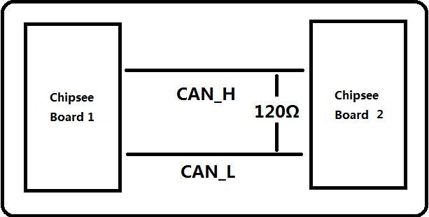
Figure 374: CAN Connect
Note
The Chipsee IPC does not mount the 120Ω matched resistor on all CAN signals by default.
Here are a few examples to test CAN by using CAN units
- Install can-utils
$ sudo apt install can-utils
- Set the bit-rate to 50Kbits/sec with triple sampling using the following command (use ROOT user):
$ sudo ip link set can0 type can bitrate 50000 triple-sampling on
- Bring up the device using the command:
$ sudo ip link set can0 up
- Transfer packets
Transmit 8 bytes with standard packet id number as 0x10
$ sudo cansend can0 -i 0x10 0x11 0x22 0x33 0x44 0x55 0x66 0x77 0x88
Transmit 8 bytes with extended packet id number as 0x800
$ sudo cansend can0 -i 0x800 0x11 0x22 0x33 0x44 0x55 0x66 0x77 0x88 - e
Transmit 20 8 bytes with extended packet id number as 0xFFFFF
$ sudo cansend can0 -i 0xFFFFF 0x11 0x22 0x33 0x44 0x55 0x66 0x77 0x88 -e --loop=20
- Receive data from CAN bus
$ sudo candump can0
- Bring down the device
$ sudo ip link set can0 down
You can use the HT application to test CAN. To perform the CAN test, you need two Chipsee IPC boards to perform the test.
Follow these steps to perform the CAN test:
Connect the two IPC boards and select the CAN port
can0orcan1simultaneously on both IPC boards.Click on the CanStart button simultaneously on both IPC boards.
Refer to the figure below for the CAN part in the HT application.

Figure 375: CAN
GPIO
There are 8 GPIOs, 4 Output, and 4 Input, they are all isolated. You can control the output or input pin voltage by feeding the VDD_ISO suite voltage. The pin voltage should be from 5V to 24V. Refer to the tables below for a detailed port definition:
Pin Number |
Definition |
|---|---|
1 |
VDD_24v |
2 |
GND_ISO |
3 |
/dev/chipsee-gpio1(out) |
4 |
/dev/chipsee-gpio2(out) |
5 |
/dev/chipsee-gpio3(out) |
6 |
/dev/chipsee-gpio4(out) |
7 |
/dev/chipsee-gpio5(in) |
8 |
/dev/chipsee-gpio6(in) |
9 |
/dev/chipsee-gpio7(in) |
10 |
/dev/chipsee-gpio8(in) |
Set GPIO1 Output to high using this command
# echo 1 > /dev/chipsee-gpio1
Set GPIO2 Output to low using this command
# echo 0 > /dev/chipsee-gpio2
Check GPIO5 value using this command
# cat /dev/chipsee-gpio5
You can use the HT application to test GPIO.
Follow these steps to perform the GPIO test:
Before you test, you need to connect the output gpio and input gpio, like pin 3 — pin 7 / pin 4 — pin 8 / pin 5 — pin 9 / pin 6 — pin10.
Don’t forget to give outside power to the pin 1 and pin2. You can use the outside 24V input power.
Click on the SetAllHigh or SetAllLow button to check the right light status.
Also, you can set the output gpio to high or low respectively. Then check the right input gpio status, as shown on the figure below.

Figure 376: GPIO Test
Note
The default gpio has 4 Outputs and 4 Inputs. If you want a custom solution, please check the /etc/init.d/chipsee-init file for details.
Buzzer
You can control the buzzer easily, with the following command:
- Enable the buzzer
# echo 1 >/dev/buzzer
- Disable the buzzer
# echo 0 >/dev/buzzer
You also can use the HT application to test the buzzer.

Figure 377: Buzzer
Development
In this chapter, you will learn how to set up the QT development environment, and develop the first QT application on Chipsee IPC boards.
Preparation
Download QT5.5.1 and install it on the system. Install it in the /home/<user>/program directory.
- Install IMX6UL SDK. Get and install the SDK by using the following commands:
# wget -c https://chipsee-tmp.s3.amazonaws.com/SDK/fsl-imx-x11-glibc-x86_64-meta-toolchain-qt5-cortexa7hf-vfp-neon-toolchain-3.14.52-1.1.1.sh
    # chmod +x fsl-imx-x11-glibc-x86_64-meta-toolchain-qt5-cortexa7hf-vfp-neon-toolchain-3.14.52-1.1.1.sh
# ./fsl-imx-x11-glibc-x86_64-meta-toolchain-qt5-cortexa7hf-vfp-neon-toolchain-3.14.52-1.1.1.sh
The default install directory is /opt/fsl-imx-x11/3.14.52-1.1.1. You can install it in this directory or you can also use another directory.
- Use the following command to test SDK:
# source /opt/fsl-imx-x11/3.14.52-1.1.1/environment-setup-cortexa7hf-vfp-neon-poky-linux-gnueabi
# echo ${CC}
- Setting Qtcreator. If you installed
qt-opensource-linux-x64-5.5.1.run, the Qtcreator will be installed automatically. - Before you open QtCreator, you need to add the following code-block in the first line of /home/<user>/program/Qt5.5.1/Tools/QtCreator/bin/qtcreator.sh, as shown on the figure below.
$ source /opt/fsl-imx-x11/3.14.52-1.1.1/environment-setup-cortexa7hf-vfp-neon-poky-linux-gnueabi

Figure 378: Setting QtCreator
- Setting Qtcreator. If you installed
- Use the following command to open Qtcreator.
# /home/program/Qt5.5.1/Tools/QtCreator/bin/qtcreator.sh


Example — Develop a HelloWorld Program
- Use QtCreator to create a new Qt Widgets Application, named
HelloWorld, as shown on the figure below. 
Figure 383: Qt Widgets Application
- Use QtCreator to create a new Qt Widgets Application, named
- Select IMX kits, as shown on the figure below.

Figure 384: Kit Selection
- Use QMainWindow as the Base class, as shown on the figure below.

Figure 385: Base Class
- Click the Design icon to add one label widget, as shown on the figure below.

Figure 386: Add Label Widget
- Click on the Build icon to build app, as shown on the figure below.

Figure 387: Build App
- Copy the
Helloworldapp to the IPC board’s /home/root/ directory and use the following command to run it: # export DISPLAY=:0.0 # ./HelloWorld
- Copy the
You can get the HelloWorld app from the /home/leave/build-HelloWorld-imx-Debug directory, but your directory might not be the same as this one.
Q&A
In this chapter, you can learn how to set up the QT development environment, and develop the first QT application on Chipsee IPC boards.
How to Change psplash’s
- Install IMX SDK and some Packages. Reference the install SDK point under the Preparation section above to install IMX SDK and install some recommends packages using this command:
$ sudo apt-get install autoconf libgdk-pixbuf2.0-dev
- Generate psplash of your own.
- Get
psplash.tar.gzfrom DVD/Linux+QT5/Tools/ and extract it. $ sudo tar zxvf psplash.tar.gz
- Get
- Prepare a PNG file, such as
chipsee.png $ sudo cp chipsee.png psplash/ $ sudo cd psplash
- Prepare a PNG file, such as
- Setting environment
$ source /opt/fsl-imx-x11/3.14.52-1.1.1/environment-setup-cortexa9hf-vfp-neon-poky-linux-gnueabi

- Generate header file and modify the psplash.c, then config and make:
$ ./make-image-header.sh chipsee.png POKY  //you will find a new file named chipsee-img.h
$ vi psplash.c  // replace the header file name (psplash-poky-img.h) in psplash.c with chipsee-img.h
$ ./autogen.sh
$ make  // you will generate the file psplash
Then you will find the file
psplash, replace the one inrootfs/usr/bin/psplash. Reboot your IPC board to apply the changes made to the psplash.You can remove the /etc/init.d/psplash.sh file in
rootfsto disable it.- If you want to rotate the psplash screen, just do the following in the system:
# echo 180 > /etc/rotation   // rotate  180  angle
# echo 0 > /etc/rotation         // reset to default.
Disclaimer
This document is provided strictly for informational purposes. Its contents are subject to change without notice. Chipsee assumes no responsibility for any errors that may occur in this document. Furthermore, Chipsee reserves the right to alter the hardware, software, and/or specifications set forth herein at any time without prior notice and undertakes no obligation to update the information contained in this document.
While every effort has been made to ensure the accuracy of the information contained herein, this document is not guaranteed to be error-free. Further, it does not offer any warranties or conditions, whether expressed orally or implied in law, including implied warranties and conditions of merchantability or fitness for a particular purpose. We specifically disclaim any liability with respect to this document, and no contractual obligations are formed either directly or indirectly by this document.
Despite our best efforts to maintain the accuracy of the information in this document, we assume no responsibility for errors or omissions, nor for damages resulting from the use of the information herein. Please note that Chipsee products are not authorized for use as critical components in life support devices or systems.
Technical Support
If you encounter any difficulties or have questions related to this document, we encourage you to refer to our other documentation for potential solutions. If you cannot find the solution you’re looking for, feel free to contact us. Please email Chipsee Technical Support at support@chipsee.com, providing all relevant information. We value your queries and suggestions and are committed to providing you with the assistance you require.