Android OS
Android OS User Manual
This manual is used to provide users with a fast guide of Chipsee Industrial Computers (Abbreviated as IPC) about Android OS development. Through this manual, users can quickly understand the hardware resources; users can build a complete compilation of Android development environment; users can debug Android OS via serial, USB OTG and Internet.
Revision |
Date |
Author |
Description |
|---|---|---|---|
V1.0 |
2021-12-09 |
Randy |
Initial Version |
SUPPORTED BOARDS:
CS80480T050 CS80600T080 CS10600T070 CS80480T070 CS10768T097
PREBUILT FILES PACKAGE:
Prebuilt files for the various industrial PCs can be found in the OS Downloads.
Below are the links to the prebuilt files for each industrial PC model.
System Features
Feature |
Comment |
|---|---|
System |
Android 4.1 |
Preparation
You will need to prepare the following items before you can start using the Prebuilt Files Package to re-flash the system.
Power Supply Unit (PSU) with the appropriate voltages, as follows:
Products with 5” display panel require 6V to 36V PSU
Products with 7” to 10.1” display panel and larger require 6V to 42V PSU
USB to serial cable for debugging Chipsee Industrial Embedded Computers (Chipsee IPC)
TF Card to create a bootable storage for re-flashing the system. Use the prebuilt files link above to re-flash the system.
Hardware Requirements
Chipsee Industrial PC
PSU according to the instructions above
USB-to-serial or other serial cable for debugging
TF Card (at least 4GB) and card reader
USB A-A cable (used only if the hardware configured as OTG)
Windows 7 PC
Software Requirements
Android OS Prebuilt Files Package (from the link above)
ADT for Windows
Android USB driver (for Windows)
Getting Started and Tests
DIP Switch Configuration
Set the boot DIP switch, as shown on the figure below, to boot the system from the external SD Card.

Figure 752: Boot Mode Setup
Downloading Images
Chipsee IPC supports booting from an integrated eMMC or an external TF Card (also known as the micro SD card). Booting from the external TF Card allows flashing the system OS.
Note
The operator should use the prebuilt file we provided in the CD to test the hardware before re-flashing the system.
Prebuilt Files Package
You can get the Prebuilt Files Package for each model from links mentioned at the beginning of this documentation. You can also get the Prebuilt Files Package from the DVD in /Android/Prebuilds folder. However, it may be outdated so always compare the versions (the last number in the filename is the release date).
The prebuilt package has the following content:
Contents |
Comment |
|---|---|
boot/imx6ulipc.dtb |
TF Card boot dtb file |
boot/u-boot.imx |
TF Card boot bootloader |
boot/zImage |
TF Card boot kernel file |
filesystem/rootfs-emmc-flasher.tar.bz2 |
TF Card boot rootFS |
mksdcard.sh |
Shell tools to make bootable TF Card |
README |
Simple guidelines |
S1.jpg |
Boot Switch Config Figure |
emmc-flash/emmc/rootfs.tar.gz |
RootFS in target eMMC |
emmc-flash/emmc/u-boot.imx |
Bootloader in target eMMC |
emmc-flash/emmc/zImage |
Kernel file in target eMMC |
emmc-flash/emmc/imx6ul-eisd.dtb |
dtb file in target eMMC |
emmc-flash/mkemmc.sh |
Shell tools to download images |
Note
The default zImage and imx6q-sabresd.dtb files support ‘keep the logo from uboot to kernel’ but do not support framebuffer.
Chipsee provides zImage_framebuffer and imx6q-eisd.dtb_framebuffer file versions that support the framebuffer function but do
not support the ‘keep the logo from uboot kernel’ feature. If you need the framebufer, just rename these two files to zImage
and imx6q-eisd.dtb.
How to make a bootable SD card
The Prebuilt Files Package has a shell tool that can help create a bootable SD card using a Linux platform (such as desktop PC or Virtual
Machine running Ubuntu 14.04 distribution).
Use the SD Card to download the bootable system image onto the Linux platform and follow the steps below to create a bootable SD card:
Copy the Prebuilt Files Package to a Linux environment (such as Ubuntu 14.04).
Insert the SD card into your computer. If you are using virtual machines, please ensure the SD card is mounted to the Linux operating system.
- Confirm the SD card mount point,
/dev/sdX,(e.g.,/dev/sdcor/dev/sdb, be sure to use the right one). In a Linux system, you can use the command below to find out what X is. $ sudo fdisk –l
- Confirm the SD card mount point,
Copy the
prebuilt-jb-hmi-XXXX.tar.gzto somewhere(such as $HOME).- Extract the
prebuilt-jb-hmi-XXXX.tar.gz $ tar -xzvf prebuilt-jb-hmi-XXXX.tar.gz
- Extract the
- Go to the folder
$ cd ~/Prebuilt-cs-androidXXXXX/prebuilt-sd/
- Use the following command to flash the Android OS to the SD card
$ sudo ./mkmmc-android.sh --device /dev/sd<?>
Note
sd<?> means the SD card mount point, (e.g.,
/dev/sdcor/dev/sdb) in Ubuntu system.The recommended SD card should be Sandisk Class4 level SD card or above.
The bootable SD Card is now ready. Power OFF the industrial PC and insert the SD Card.
Set the DIP switch to uSD BOOT mode. (refer to DIP Switch Configuration above)
Connect the industrial PC to PC via COM1. Power ON the IPC.
After 20 minutes, if the LED on industrial PC stays lit, flashing is completed. Using COM1, you can also find this message >>>>>>> eMMC Flashing Completed <<<<<<< which indicates that the system image was downloaded correctly to the eMMC.
Power OFF the IPC and set the DIP switch to eMMC BOOT mode. (refer to DIP Switch Configuration above)
How flash Android to NAND
The Prebuilt Files Package has a shell tool that can help create a bootable NAND card using a Linux platform (such as desktop PC or Virtual
Machine running Ubuntu 14.04 distribution).
Follow the steps below to create a bootable NAND card:
Copy the Prebuilt Files Package to a Linux environment (such as Ubuntu 14.04).
Insert the SD card into your computer. If you are using virtual machines, please ensure the SD card is mounted to the Linux operating system.
- Confirm the SD card mount point,
/dev/sdX,(e.g.,/dev/sdcor/dev/sdb, be sure to use the right one). In a Linux system, you can use the command below to find out what X is. $ sudo fdisk –l
- Confirm the SD card mount point,
Copy the prebuilt file
prebuilt-jb-hmi-XXXX.tar.gzto somewhere(such as $HOME).- Extract the prebuilt file
prebuilt-jb-hmi-XXXX.tar.gz $ tar -xzvf prebuilt-jb-hmi-XXXX.tar.gz
- Extract the prebuilt file
- Go to the folder
prebuilt-jb-hmi-XXXX/prebuilt-nand/ $ cd ~/prebuilt-jb-hmi-XXXX/prebuilt-nand/
- Go to the folder
- Use the following command to flash the Android OS to the NAND card
$ sudo ./mkmmc-android-nand.sh --device /dev/sd<?>
Note
sd<?> means the SD card mount point, (e.g.,
/dev/sdcor/dev/sdb) in Ubuntu system.The recommended SD card should be Sandisk Class4 level SD card or above.
The bootable NAND Card is now ready. Power OFF the industrial PC and insert the NAND Card.
Set the DIP switch to NAND BOOT mode. (refer to DIP Switch Configuration above)
Connect the industrial PC to PC via COM1. Power ON the IPC.
After 20 minutes, if the LED on industrial PC stays lit, flashing is completed. Using COM1, you can also find this message >>>>>>> eMMC Flashing Completed <<<<<<< which indicates that the system image was downloaded correctly to the eMMC.
Power OFF the IPC and set the DIP switch to eMMC BOOT mode. (refer to DIP Switch Configuration above)
Start Android OS
The first time you start Android OS on the industrial PC will take a little time. But after the first time, Android OS will start quickly. When the Android OS starts up, you will see the Chipsee Logo on the LCD screen. It is a successful start if you see the Android OS desktop such as the one shown in the figure below:

Figure 753: Android OS start-up screen
Tests
Touch screen test
Run MultiTouch Tester App.
The screen will show the number and position of the touch point when touching the screen.
Note
Resistive screen expansion board only supports single-touch, and capacitive screen expansion board supports five-point touch as described in the figure below.
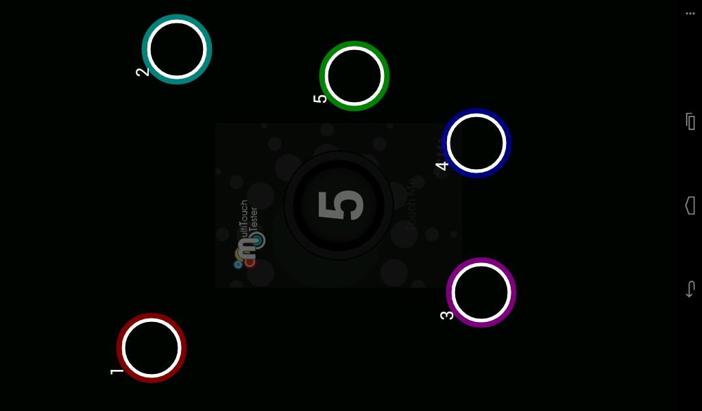
Figure 754: Touch screen test (Capacitive touch)
After working for some time, the resistive touch screen may not be accurate. The user must run a touch screen calibration test.
Run Chipsee TouchCal App as described in the figure below.

Figure 755: Touch screen calibration test (Resistive touch)
Buzzer test
Run Chipsee Buzzer App.
Push the “OpenBuzzer” button to start the buzzer sound.
Push the “CloseBuzzer” button to stop the sound.
Gravity sensor test
You can test the gravity sensor by whirling the screen.
Run SensorList App.
In the “Analog Device 3 axis accelerometer” option, you can see real-time changes of the three-axis acceleration value curve, as shown on the figure below.

Figure 756: Real-time acceleration curve
You can also test gravity using a gravity sensing game, such as “NFS shift” or “Tilt 3D laby”. If you use “NFS shift”, please run the ChipseeSensorTool app to adjust the direction of the axis by selecting “Invert X-axis” and “Swap X/Y axes”. If you use other games, please adjust the settings as default.
Audio IO test
Insert the microphone and earphones into the Audio IO interface (Audio IN coloured pink, Audio OUT coloured light blue).
Start Talking Tom App (Tom Cat).
Speak into the microphone, Tom the cat will repeat spoken content.
Serial test
There are four serial ports on the Chipsee IPC: 2 X RS232 and 2 X RS485. Refer to the table below for the available serial device nodes.
Ports |
Device Node |
|---|---|
COM1(RS232, Debug) |
/dev/ttyO0 |
COM2(RS232) |
/dev/ttyO1 |
COM3(RS485) |
/dev/ttyO2 |
COM4(RS485) |
/dev/ttyO4 |
You can install the SecureCRT or Putty software on a Windows 7 PC to test the serial ports by following these steps:
Connect COM1 on industrial PC board to Windows 7 PC.
Run Serial Port API App to communicate with Windows 7 PC, as shown on the figure below.

Figure 757: Serial settings
Push the button with the label “Send 01010101”, you will see something on the Windows 7 PC that looks similar to the figure below.
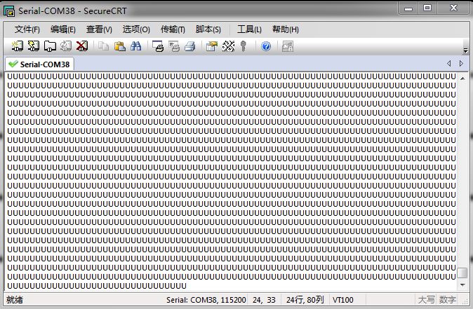
Figure 758: Serial send test
Push the button with the label “Console”, to send whatever you like as shown on the figure below.
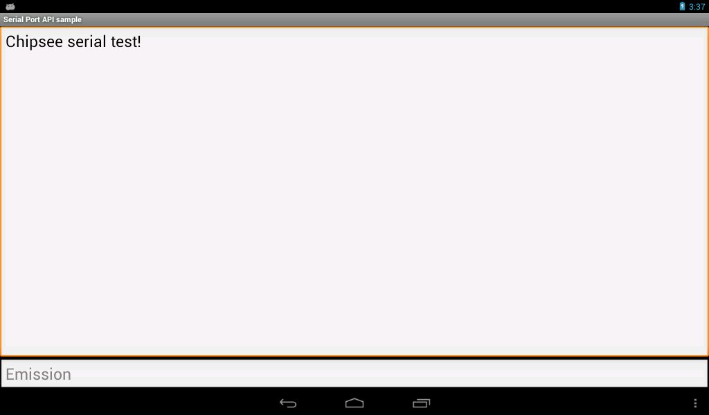
Figure 759: Serial receive test
USB device test
USB-WiFi
The Android OS supports USB-WiFi (RTL8188). You can find the device in settings, as shown on the figure below.

Figure 760: USB-WiFi
USB-Camera
The Android OS supports USB-Camera. You can find the device in settings, as shown on the figure below.

Figure 761: USB-Camera
Modify OS Start up Logo
Chipsee® provides a software to change the OS boot up logo. The software ChipSee_LOGO_MOD_EN.exe is provided on the CD for a product.
To change the logo, follow these steps:
- Open the software:
Chipsee_LOGO_MOD_EN.exein Windows 
Figure 762: Chipsee OS Boot-up Logo Modify Software
- Open the software:
- Click the first Browse button. Select the picture file you want to use as the logo.

Figure 763: Choose the Logo you want
- Click the second Browse button. Select the
u-boot.imgfile you want to use. 
Figure 764: Choose the u-boot.img file
- Click the second Browse button. Select the
- Choose the correct resolution for your product, then click Execute.

Figure 765: Change the Logo successful
Insert the SD card into the IPC. Power ON the IPC and the Logo will be replaced.
IP settings
To make changes to the IP address, follow these steps:
Search the boot partition for the
uEnv.txtfile.- Open and edit the file
uEnv.txtwith any text editor. bootargs=console=ttyO0,115200n8 androidboot.console=ttyO0 mem=512M root=/dev/mmcblk0p2 rw rootfstype=ext4 rootwait init=/init ip=off
- Open and edit the file
- Edit the part with ip=value, where value = off OR <iPv4 address>:::<Subnet mask>
For example: .. code:
bootargs=console=ttyO0,115200n8 androidboot.console=ttyO0 mem=512M root=/dev/mmcblk0p2 rw rootfstype=ext4 rootwait init=/init ip=192.168.1.111:::255.255.0.0
Note
Inputting wrong details could harm the industrial PC and because of that you should backup the file before making any changes. This can help you reverse changes easily if an error occurs.
Android system debug in Windows
In this section, we will discover how to view the Android system via the serial port and debug the system via USB OTG.
Also, we will discover how to install and uninstall applications via USB OTG.
The following operation is under the Windows 7 x64 environment, similar to other Windows platforms.
View Android system via the serial port
Install the SecureCRT or Putty software on a Windows 7 PC to view the Android system via the serial ports.
Follow these steps to view Android system via the serial port:
Connect COM1 on the industrial PC board to Windows 7 PC.
Open the SecureCRT or Putty software on the Windows 7 PC.
Power ON the industrial PC. You will see the serial output information as shown on the figure below.

Figure 766: Serial output information
Adb connect via USB OTG
Download Oracle JDK 6 and Android Studio SDK for Windows. We suggest you download JDK-6u45.
Install Oracle JDK 6 and Android Studio SDK for Windows.
Extract the file somewhere (the name for the extracted folder is ADT).
The ADB command is in the
<ADT>\sdk\platform-toolsfolder.- Optionally, you can add the location of the SDK’s primary tools directory to your system PATH by following these steps:
Right-click on My Computer, and select Properties.
Under the Advanced tab, hit the Environment Variables button.
In the dialogue that comes up, double-click on Path (under System Variables).
Add the full path to the toolsdirectory to the path.
- Install Android USB driver on Windows:
Copy the
usb_driverfolder on the CD to a folder on the Windows 7 PC.Boot the board as normal and wait until shell prompt is available (disconnect the micro-B USB cable).
Connect a micro-B USB cable between the board and Windows 7 PC.
If it is proceeding as planned, Windows will recognise the new hardware and ask you to install drivers for it.
Right click on the hardware. Click on install driver.
Choose the answer No, not this time to the question about running Windows Update to search for software.
Choose Install the hardware that I manually select from a list (Advanced) this is the 2nd option, then click Next.
Browse to your driver folder (
\usb_driver). and look for a.inffile.Select
android_winusb.infand click Open then OK. It’s the only file in the folder, so you shouldn’t go wrong.Select Android ADB Interface then click the Next button.
A warning will appear, answer Yes but read the warning, anyway.
When the wizard finishes, click the Close button .
Now you can see it installed the driver successfully, as shown on the figure below.

Figure 767: ADB Driver
- Test ADB by following these steps:
Press the Win+r key combination to open the Run Command dialogue box.
Type cmd and press enter.
Execute the commands below in the command prompt.
> cd <ADT>\sdk\platform-tools\
> adb kill-server
> adb start-server
> adb devices
> adb shell
If the
#prompt appears at the beginning of the command line, it means we connected the industrial PC with the Windows 7 PC successfully as shown on the figure below.

Figure 768: ADB Command
Now you can use Linux commands like
ls,cdand so on. Press Ctrl + C to exit the shell and return to the Windows system.
- Use the
adbcommand to install an Android App: for example SogouInput.apk. If there is a SUCCESS message, as shown on the figure below, then the app installation was successful. > adb install SogouInput.apk
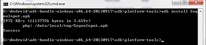
Figure 769: Install App
- Use the
- Use
adbcommand to uninstall an Android app: for example SogouInput.apk. Follow these commands to uninstall an app. > adb shell pm list packages > adb uninstall com.sohu.inputmethod.sogou
The
pm listcommand gets the full name of the app, as shown on the figure below.
Figure 770: Command
pm listto get app’s name¶The
uninstallcommand uninstalls the app from the Android system.Delete the apk file for the app by using these commands:
> adb shell
# cd /system/app/
# ls
# rm Browser.apk
- Use
- Use
adbcommand to transport files between the industrial PC and Windows 7 PC. Transfer file from the industrial PC to Windows 7 PC using
adb pullcommand.
> adb pull <pathTo_file_on_board> <pathTo_store_file_on_PC>
Transfer file from the Windows 7 PC to the industrial PC using
adb pushcommand.
> adb push <pathTo_file_on_PC> <pathTo_store_file_on_board>
- Use
Adb connect via internet
- The Ethernet port on the industrial PC and the host machine (Windows 7 PC) should connect to the network. Check Ethernet configuration for the industrial PC using the command below.
# netcfg
lo       UP    127.0.0.1       255.0.0.0       0x00000049
eth0     UP    192.168.1.117/24   255.255.252.0   0x00001043
- If the industrial PC’s Ethernet is not configured, configure the Ethernet using the
ifconfig/netcfgcommand as shown below. # netcfg eth0 dhcp
- If the industrial PC’s Ethernet is not configured, configure the Ethernet using the
- Configure the ADB Daemon to use an Ethernet connection using the
setpropcommand, as shown below. # setprop service.adb.tcp.port 5555
- Configure the ADB Daemon to use an Ethernet connection using the
- If the network is configured successfully using the steps above, then Restart
service adbdon the Windows 7 PC. # stop adbd # start adbd
- If the network is configured successfully using the steps above, then Restart
- On the host machine (Windows 7 PC) use the following commands to establish the
adbconnection. $ adb kill-server $ adb start-server $ adb connect :5555
- On the host machine (Windows 7 PC) use the following commands to establish the
- Verify the device connectivity, by executing the following commands. If connected, find the device name listed as``IPADDRESS:PORT``.
$ adb devices
List of devices attached
emulator-5554    device
192.168.1.117:5555  device
- An example of using the
adbcommand to install software for Android. Make sure the"**".apkfile is at the current folder, and export the adb path. Use the argument
–sto assign the device to use over the internet.
$ adb –s 192.168.1.117:5555 install "**".apk
- An example of using the
Android App Development
In this section, we will introduce the development of an Android app with Eclipse on Windows. We assume that the USB is OTG model and the driver is already installed. (See Adb connect via USB OTG)
Preparation
Download and install Eclipse IDE.
- Go to the
/eclipsefolder, start eclipse.exe. 
Figure 771: Start eclipse
- Go to the
- Click Windows–>Android SDK Manager to open SDK Manager.

Figure 772: Android SDK Manager
- Click Tools–>Options, check the
Forcebox and click close. 
Figure 773: Android SDK Manager Settings
- Click Tools–>Options, check the
- Choose the API, such as Android4.2.2(API 17), then click the Install packages button to start the download and installation of API packages.

Figure 774: Install API packages
Downloading and installing the packages will take some time. When the process completes, close the Android SDK Manager.
Example — Develop a HelloWorld Program
- Click File–>New–>Android Application Project

Figure 775: New Application
- Click on the Next button until the app project is created. Connect the industrial PC to Windows 7 PC via the USB cable (A-A). If the connection is successful, you will see the device in the DDMS window (Windows–>Open Perspective–>Other–>DDMS)

Figure 776: DDMS
- You can capture the desktop of Android

Figure 777: Capture Android Desktop
- Click run, and choose the device

Figure 778: Run HelloWorld Program
- Result

Figure 779: HelloWorld Program
Note
If the USB is not configured as an OTG model, you can copy and install the file HelloWorld.apk from the project folder HelloWorld/bin/, or install the HelloWorld.apk via the internet (See Adb connect via internet).
Disclaimer
This document is provided strictly for informational purposes. Its contents are subject to change without notice. Chipsee assumes no responsibility for any errors that may occur in this document. Furthermore, Chipsee reserves the right to alter the hardware, software, and/or specifications set forth herein at any time without prior notice and undertakes no obligation to update the information contained in this document.
While every effort has been made to ensure the accuracy of the information contained herein, this document is not guaranteed to be error-free. Further, it does not offer any warranties or conditions, whether expressed orally or implied in law, including implied warranties and conditions of merchantability or fitness for a particular purpose. We specifically disclaim any liability with respect to this document, and no contractual obligations are formed either directly or indirectly by this document.
Despite our best efforts to maintain the accuracy of the information in this document, we assume no responsibility for errors or omissions, nor for damages resulting from the use of the information herein. Please note that Chipsee products are not authorized for use as critical components in life support devices or systems.
Technical Support
If you encounter any difficulties or have questions related to this document, we encourage you to refer to our other documentation for potential solutions. If you cannot find the solution you’re looking for, feel free to contact us. Please email Chipsee Technical Support at support@chipsee.com, providing all relevant information. We value your queries and suggestions and are committed to providing you with the assistance you require.