EPC/PPC-A8-097-C
Note
EOL PRODUCT: This product has been discontinued, due to market demand and shifts in technology. Please Contact us if you would like to purchase it.
Version 1.1


Product Overview
The Cortex®-A8 series EPC/PPC-A8-097-C (PN: CS10768T097) is a high-quality industrial PC. It features a 9.7” resistive touch screen with a resolution of 1024 x 768 pixels and brightness of 350 cd/m2.
It is available both as an embedded solution and as a device hosed in an aluminum casing with bezels, thus facilitating different installation options:
Installation on an industrial cabinet
Integration with the existing equipment
The EPC/PPC-A8-097-C Industrial PC is based around the powerful CS-SOM335X-V3 System on Module (SoM), powered by the AM3354 Arm® Cortex®-A8 microprocessor unit (MPU). The AM33554 MPU is enhanced with image, graphics processing, peripherals and industrial interface options such as EtherCAT and PROFIBUS. The devices support high-level operating systems (HLOS).
The microprocessor unit (MPU) subsystem is based on the ARM Cortex-A8 processor and the PowerVR SGX™ Graphics Accelerator subsystem provides 3D graphics acceleration to support display and gaming effects.
The AM33554 MPU does not generate extensive heat, so even the thin aluminum housing on PPC version delivers sufficient thermal dissipation.
Ordering Options
Chipsee products can be customized during the ordering process. The product will be shipped with the pre-installed factory defaults if no extra requirements are specified. The table in the Hardware Features section provides information about the default options bundled with the product.
Note
You can order EPC/PPC-A8-097-C from the official Chipsee Store or from your nearest distributor.
Operating System
This product comes with a pre-installed OS of your choice. Please see the list below for the supported OSes, which can be also obtained from the Software Documentation section, along with the detailed installation instructions.
Android 4.1
Linux with Qt 4.8
Linux with Qt 5.5
Debian 7.4
Debian 8.4
Angstorm v2012.12
Warning
The Software Documentation section provides a detailed instruction how to install different OS on your own. However, bear in mind that Chipsee can’t take the responsibility of inadequate installation procedure. If you “brick” your device, please contact Chipsee Technical Support at support@chipsee.com for further assistance
Optional Features
The EPC/PPC-A8-097-C Industrial PC does not include WiFi/BT and/or 3G/4G modules by default. The Wi-Fi/BT module is optional and can be selected during the ordering process.
A 3G/4G LTE module is not available at the Chipsee store for this product. However, it can be obtained from specialized third-party suppliers.
Warning
Hardware Features
The EPC/PPC-A8-097-C Industrial PC offers a board range of performance and connectivity options for scalable integration, providing expandability according to future needs. Some of the key features are listed in the table below.
EPC/PPC-A8-097-C |
|
|---|---|
CPU |
AM3354ZCZ100, Arm® Cortex®-A8, 1GHz |
RAM |
512MB DDR3 |
eMMC |
4GB |
Storage |
TF Card, Supports up to 32GB SDHC |
Display |
9.7” LCD, 1024 x 768 resolution px, brightness 350 cd/m2 |
Touch |
5-point capacitive touch screen |
USB |
3 x USB 2.0 Host, 1 x USB OTG |
LAN |
1 x Channel 100M LAN |
Audio |
3.5mm output/input connector, 2W Internal Speaker |
Buzzer |
Yes |
RTC |
Yes |
RS232 |
2 x RS232 |
RS485 |
2 x RS4851 |
CAN |
1 x CAN1 |
GPIO |
8 Channels |
WiFi/BT |
Onboard WiFi/BT (optional) |
Expansion Port |
N/A |
3G/4G/LTE |
WCDMA+GPS Module (optional) |
Power Input |
From 6V to 42V |
Current at 12V |
800mA Max |
Power Consumption |
7W Typical |
Working Temperature |
From -20°C to +70°C |
OS |
Multiple Choices (Operating System) |
Dimensions |
EPC-A8-097-C (PN: CS10768T097E): 226 x 172 x 28mm |
PPC-A8-097-C (PN: CS10768T097P): 252 x 205 x 33mm |
|
Weight |
EPC-A8-097-C (PN: CS10768T097E): 610g |
PPC-A8-097-C (PN: CS10768T097P): 1260g |
|
Mounting |
EPC-A8-097-C (PN: CS10768T097E): Embedded |
PPC-A8-097-C (PN: CS10768T097P): Panel |
|
Power Input
The EPC/PPC-A8-097-C Industrial PC can be powered by a wide range of input voltages: From 6V to 42V DC. The power input connector is a 3-pin, 3.81mm terminal. The polarity and the pinout is clearly marked on the housing of the PPC version, as well as on the PCB itself of the EPC version, as shown in the figure below.

Figure 736: Power Input (embedded/enclosed version)
Note that the “+” sign represents the positive power input, and it is printed both at the casing and as a silk-screen on a PCB of the embedded version. The “-” terminal is shorted to the ground.
Power Input Definition |
||
|---|---|---|
Pin Number |
Definition |
Description |
Pin 1 |
Positive Input |
DC Power Positive Terminal |
Pin 2 |
Negative Input |
DC Power Negative Terminal |
Pin 3 |
Ground |
Power System Ground |
Note
The system ground “G” is connected to power negative “-” on board.
Touch Screen
The EPC/PPC-A8-097-C Industrial PC uses a 5-point capacitive touch screen screen. The figure below shows the capacitive or resistive screen connected to the motherboard via the FPC connector.

Figure 737: Capacitive or Resistive Touch Connector
Attention
A capacitive touch screen is susceptible to power noise and Electromagnetic Radiation (EMR). It may cause LCD ripples or even capacitive touch malfunction. If using a capacitive multi-touch test application, you might notice the touch points float erratically across the display. There are several solutions to this problem:
Use a high-quality Power Adapter Unit (PSU) with low EMR. You can also provide power from a battery.
Make sure that the EPC/PPC-A8-097-C Power Input connector (pin 3) is properly connected to the Power System Ground to provide sufficient EMI shielding and eliminate the problem entirely.
Bad GND problem can also be confirmed by touching pin 3 of the Power Input connector with one hand while operating the capacitive touch screen with the other hand. In this case, the operator’s body acts as the Power System Ground.
Connectivity
There are many connectivity options available on the EPC/PPC-A8-097-C industrial PC. It has 3 x USB 2.0 Host, 1 x USB OTG (can be customized to 2 x Host), 1 x Channel 100M LAN (RJ45) Ethernet connector supporting up to 1 Gbps, and 5 x UART terminals (RS232/RS485).
RS232/RS485/CAN
The serial communication interfaces (RS485, RS232, and CAN) are routed to a 12-pin 3.81mm terminal, as illustrated on the figure below.

Figure 738: Relation between serial pins on embedded vs. enclosed version of the EPC/PPC-A8-097-C Industrial PC
The table below offers more detailed description of every pin and its definition:
RS232 / RS485 / CAN Pin Definition: |
||
|---|---|---|
Pin Number |
Definition |
Description |
Pin 12 |
+5V |
Isolated +5V Power Output, No more than 200mA Current output |
Pin 11 |
RXD1 |
UART0 of CPU, RS232 RXD Signal |
Pin 10 |
TXD1 |
UART0 of CPU, RS232 TXD Signal |
Pin 9 |
RXD2 |
UART1 of CPU, RS232 RXD Signal |
Pin 8 |
TXD2 |
UART1 of CPU, RS232 TXD Signal |
Pin 7 |
B1 |
UART2 of CPU, RS485 B Signal |
Pin 6 |
A1 |
UART2 of CPU, RS485 A Signal |
Pin 5 |
B2 |
UART4 of CPU, RS485 B Signal |
Pin 4 |
A2 |
UART4 of CPU, RS485 A Signal |
Pin 3 |
CAN_H |
DCAN0 of CPU, CAN H Signal |
Pin 2 |
CAN_L |
DCAN0 of CPU, CAN L Signal |
Pin 1 |
GND |
Isolated Ground Output |
USB Connectors
There are 4 x Type A USB HOST connectors onboard, as shown on the figure below.

Figure 739: USB HOST Connectors (embedded/enclosed PC version)
Note
The USB Connectors are defined as HOST by default. If customer needs it work as OTG (slave), please solder a 0Ω 0603 Package Resistor to R140 and R138.
Warning
Be careful not to touch surrounding electronic components accidentally while plugging in USB devices into the embedded Industrial PC version.
LAN Connectors
LAN (RJ45) connector provides Ethernet connectivity over standardized Ethernet cables as shown the figure below. The integrated Ethernet interface supports up to 1 Gbps data throughput.

Figure 740: RJ45 LAN Connectors (embedded/enclosed PC version)
Note
Use CAT5 or better cables to achieve full data throughput over maximum distance defined by the 1000BASE-T standard (100m).
WiFi & BT Module
The EPC/PPC-A8-097-C Industrial PC is equipped with the popular Realtek RTL8723 WiFi/BT module that supports BT/BLE 4.0 (with backward compatibility), as well as 802.11bgn 2.4 GHz Wireless LAN (WLAN).
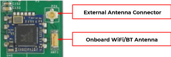
Figure 741: RTL8273 WiFi/BT Module
The enclosed (PPC) variant of the product also includes an SMA connector for an external WiFi/BT antenna, as illustrated in the figure below.

Figure 742: WiFi+BT Antenna
Note
The product does not come shipped with the WiFi/BT module by default.
If the operator mounts the WiFi/BT module on the EPC/PPC-A8-097-C industrial PC, the module uses the USB1 channel to communicate with CPU, so it will occupy the USB1 channel.
3G/4G/LTE Module
The EPC/PPC-A8-097-C Industrial PC is equipped with a mini-PCIe connector that can connect to a 3G/4G/LTE module. The customer will also need a SIM Card Holder and a 3G/4G/LTE Antenna Connector to ensure 3G/4G/LTE works on the EPC/PPC-A8-097-C.
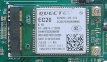
Figure 743: 3G/4G/LTE Module
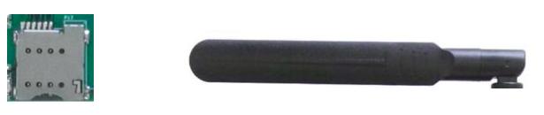
Figure 744: SIM Card Holder and 3G/4G/LTE Antenna Connector
Attention
The product does not come shipped with the 3G/4G module by default.
GPIO Port
The EPC/PPC-A8-097-C Industrial PC has a 10 Pin 3.81mm GPIO Connector, as shown on the figure below, that is labeled as P18 on the PCB. The table below gives details about the definition of every Pin.

Figure 745: GPIO Connector
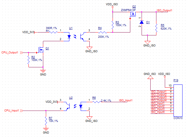
Isolated GPIO reduced schematic
GPIO Connector Pin Definition: |
||
|---|---|---|
Pin Number |
Definition |
Description |
Pin 1 |
VCC |
Isolated Power +5V Output |
Pin 2 |
GND |
Isolated Ground |
Pin 3 |
OUT1 |
Isolated Output 1 |
Pin 4 |
OUT2 |
Isolated Output 2 |
Pin 5 |
OUT3 |
Isolated Output 3 |
Pin 6 |
OUT4 |
Isolated Output 4 |
Pin 7 |
IN1 |
Isolated Input 1 |
Pin 8 |
IN2 |
Isolated Input 2 |
Pin 9 |
IN3 |
Isolated Input 3 |
Pin 10 |
IN4 |
Isolated Input 4 |
Attention
The GPIO has been Opt-Isolated and it uses the 24V Logic by default. The GPIO is driven by the on board VDD, you do not need an external isolated power input.
The 4 output channels can drive at most 500mA current on each channel.
The operator can use the power input that connects to Power Input Connector, if the operator doesn’t want to use an isolated power input.
Also, you can use the 5V voltage on-board as power input. The operator must solder a 0Ω resistor on R292 & R293 then you can connect the 5V voltage onboard to the Isolated Power Input Pin.
TF Card Slot
The EPC/PPC-A8-097-C Industrial PC features 1 x TF Card (micro SD) slot. It can address up to 32GB of memory.

Figure 746: TF (micro SD) Card Slot
Note
The product does not come shipped with the TF Card by default.
Audio Connectors
The EPC/PPC-A8-097-C Industrial PC features some audio peripherals, as well. It has 1 x 3.5mm audio input jack and 1 x 3.5mm audio output jack.
On the embedded panel PC version, the pink connector is the audio input jack (line-in) and the blue connector is the audio output jack (line-out, typically around -10 dBV). On the enclosed panel PC version, both audio input and audio output are clearly marked on the figure below.

Figure 747: Audio I/O (embedded/enclosed PC version)
In addition, EPC/PPC-A8-097-C features a miniature 2W embedded speaker for audio reproduction, as well as a small buzzer for alarm/notification sounds.

Figure 748: 2W Micro Speaker and Buzzer
Boot DIP Switch
The EPC/PPC-A8-097-C Industrial PC supports boot from SD card. If you want to reflash the Operating System (OS), you can use the TF card for that purpose, combined with the DIP switch settings as illustrated in the figure below.
There is no need to alter the DIP switch settings during regular operation. However, if you need to reinstall the OS, please refer to the table below. Detailed information on how to re-flash the OS can be found in the Software Documentation.

Figure 749: Boot DIP Switch
Boot Config Select |
||||
|---|---|---|---|---|
DIP SW |
1 |
2 |
3 |
4 |
SD |
1 |
0 |
0 |
0 |
eMMC |
1 |
1 |
0 |
1 |
Download |
0 |
1 |
1 |
0 |
Mounting Procedure
The EPC/PPC-A8-097-C Industrial PC can be mounted with 8 x M4 screws, enabling simplified installation onto any standard mounting fixture. Other mounting options might also be supported according to the table in the Hardware Features section.
You can find detailed information about mounting in the Mount IPC Guide.
Mechanical Specifications
EPC-A8-097-C
The outer mechanical dimensions of EPC-A8-097-C are 226 x 172 x 28mm (W x L x H). Please refer to the technical drawing in the figure below for details related to the specific product measurements.

Figure 750: EPC-A8-097-C Technical Drawing
PPC-A8-097-C
For PPC-A8-097-C, the outer mechanical dimensions are 252 x 205 x 33mm (W x L x H).
Panel Mounting

Figure 751: Fixing PPC-A8-097-C industrial PC into panel
Note
With the PPC-A8-097-C industrial PC, the operator can fix the PC into the panel by pushing it from the front inside the panel as described in the figure above. The recommended maximum thickness of the panel material is 8mm.
Make sure the Panel PC is configured correctly. The Boot Switch is sitting inside the housing. To use it, the Panel PC has to be unmounted from the panel.
Push the Panel PC straight into the Panel Hole until the unit sits flat on the panel as shown in the figure above.
Use the mounting fixtures to lock the Panel PC into it’s place.
Disclaimer
This document is provided strictly for informational purposes. Its contents are subject to change without notice. Chipsee assumes no responsibility for any errors that may occur in this document. Furthermore, Chipsee reserves the right to alter the hardware, software, and/or specifications set forth herein at any time without prior notice and undertakes no obligation to update the information contained in this document.
While every effort has been made to ensure the accuracy of the information contained herein, this document is not guaranteed to be error-free. Further, it does not offer any warranties or conditions, whether expressed orally or implied in law, including implied warranties and conditions of merchantability or fitness for a particular purpose. We specifically disclaim any liability with respect to this document, and no contractual obligations are formed either directly or indirectly by this document.
Despite our best efforts to maintain the accuracy of the information in this document, we assume no responsibility for errors or omissions, nor for damages resulting from the use of the information herein. Please note that Chipsee products are not authorized for use as critical components in life support devices or systems.
Technical Support
If you encounter any difficulties or have questions related to this document, we encourage you to refer to our other documentation for potential solutions. If you cannot find the solution you’re looking for, feel free to contact us. Please email Chipsee Technical Support at support@chipsee.com, providing all relevant information. We value your queries and suggestions and are committed to providing you with the assistance you require.